Mihir Raj RathoreMechanical engineer · M.Eng.
Domain B → Master's project · TH Rosenheim · 03/2024–08/2024

Virtual CNC machining of an additively manufactured valve body

Academic · individual projectVirtual onlySchematic graphics

Plan the machining of an additively manufactured SS316L hydraulic valve body, and check the plan virtually in Siemens NX CAM.

Project “Additive Manufacturing of LBM Parts”. Floor facing, planar milling and threading operations, with toolpaths, simulation and collision checks in Siemens NX CAM. No physical machining was performed.

VIRTUAL A · AM STARTING FORM generic build-layer lines B · SIMPLIFIED SETUP existing fixtures, provided (not designed by me) SCHEMATIC · ILLUSTRATIVE · NOT TO SCALE

SchematicOriginal drawing. Generic geometry, not the real part; not a screenshot. Left: generic build-layer lines. Right: existing fixtures, provided (not designed by me).

I developed the virtual CNC machining process and simulation in Siemens NX CAM.

Physical machining trials were not conducted.
Simulated / virtualDone in Siemens NX CAM: process planning, toolpaths, simulation, collision checks.
Physical machiningNot performed. Hatched elements on this page mark what was not done.
1 · What I built

A virtual machining process, from the additive part to a simulated result

I developed the virtual CNC machining process and simulation in Siemens NX CAM. Everything in the chain below happened on screen.

  1. 01Additive partSS316L valve body, laser beam melting (LBM)
  2. 02 · VIRTUALVirtual machining strategyFacing, planar milling, threading; tool selection
  3. 03 · VIRTUALSimulated toolpathsToolpaths generated in NX CAM
  4. 04 · VIRTUALCollision checkingChecks run in NX CAM
  5. 05 · VIRTUALVirtual evaluationSimulation only; no measured result
Project
“Additive Manufacturing of LBM Parts”, TH Rosenheim
Period
03/2024–08/2024
Format
Individual Master's project
NX CAM
Learned during the project
2 · Process explorer

Seven stages of the virtual process

Step through the sequence. The drawing is an original schematic of generic geometry. It shows how the stages relate; it is not the real part and not an NX screen.

    VIRTUAL virtual machine table existingfixture AM starting form (generic) build-layer lines generic block, not the real geometry XZWCS virtual setup in NX CAM fixtures provided,not designed by me 1 · floor facing generic flat face, illustrative path 2 · planar milling abstract zig-zag path, illustrative 3 · thread milling abstract helical path, illustrative collision check envelope vs fixture and part illustrative, no measured value SIMULATED / VIRTUAL process checked on screen PHYSICAL MACHINING NOT PERFORMED SCHEMATIC · ILLUSTRATIVE · NOT TO SCALE · NOT THE REAL PART
    Stage 1 / 7
    Stage 1 / 7 · Part

    The additive part

    The starting point is an additively manufactured hydraulic valve body in SS316L, built by laser beam melting (LBM).

    The drawing is a generic block with build-layer lines. It shows the idea of an additive starting form, not the real geometry.

    Schematic
    Stage 2 / 7 · Setup

    Machining setup

    The part is placed in a virtual machining setup in NX CAM. Existing fixtures were integrated into the setup and checked for clamping, accessibility and collisions.

    Fixtures were integrated into the setup; I did not design them.

    VirtualFixtures provided · not my design
    Stage 3 / 7 · Operation 1

    Floor facing

    The first operation is floor facing. NX CAM generates the toolpath for it, with the tool selected for the operation.

    • cutter Ø 8 mm
    • Vc 80 m/min
    • ≈ 3180 rpm
    • fz 0.02 mm
    • feed 255 mm/min
    • stepover 60 %
    Planned parametersNot verified by cutting
    Stage 4 / 7 · Operation 2

    Planar milling

    The second operation is planar milling, also planned and simulated in NX CAM.

    • Vc 30 m/min
    • ≈ 1190 rpm

    Only these two values are shown. Other values for this operation are not published here.

    Planned parametersNot verified by cutting
    Stage 5 / 7 · Operation 3

    Thread milling

    The third operation is threading: thread milling with a thread mill, G1/4. The cutter diameter is about 9.9 mm, derived from the report's cutting data (not a catalogue value).

    • Vc 60 m/min
    • 1930 rpm
    • fz 0.01 mm
    • contour feed 77.2 mm/min
    Planned parametersNot verified by cutting
    Stage 6 / 7 · Check

    Collision check

    Collision checks were run in NX CAM as part of the virtual process, including the fixtures in the setup.

    The drawing shows the idea of a clearance envelope around the tool and holder. It shows no measured clearance. Section 4 has an interactive version.

    VirtualIllustrative
    Stage 7 / 7 · Result

    Simulation

    Each operation was simulated in NX CAM. The outcome is a virtual process. No part was machined, so there is no physical result to compare it with.

    Real NX output from the report is shown in section 4.

    Simulated / virtualPhysical machining: not performed
    Planned parametersNot verified by cutting

    Planned cutting parameters used as simulation inputs

    Planned cutting parameters used as simulation inputs; not verified by cutting.
    OperationCutter ØVcSpindlefzFeed
    Floor facing8 mm80 m/min3180 rpm0.02 mm255 mm/min, stepover 60 %
    Planar millingnot shown30 m/min≈ 1190 rpmnot shownnot shown
    Thread milling (G1/4)≈ 9.9 mm ¹60 m/min1930 rpm0.01 mm77.2 mm/min contour feed

    “Not shown” means the value is not published on this page. No depth of cut is shown for any operation.

    ¹ Derived, not a catalogue value: 60 m/min at 1930 rpm gives about 9.9 mm, and the ratio of the report's centre-path feed (19.1) to contour feed (77.2) gives the same diameter for a G1/4 thread.

    3 · Setup and fixtures

    Existing fixtures were integrated; I did not design them

    The setup brings the part, the provided fixtures and the tool into one virtual scene, so that clamping, accessibility and collisions can be checked.

    VIRTUAL virtual machine table EXISTING FIXTUREprovided,not my design ① clamping ② accessibility (tool access) ③ collisions SCHEMATIC · ILLUSTRATIVE · NOT TO SCALE

    SchematicOriginal drawing of generic geometry. The callouts name the checks; they show no result.

    What I did

    Fixtures were integrated into the setup; I did not design them.

    • Integrated and checked existing fixtures (clamping, accessibility, collisions).
    • Developed the virtual machining process and simulation around that setup in NX CAM.
    What I did not do
    • Design or model the fixtures. They were provided.
    • Clamp a real part on a real machine.
    4 · Toolpaths and simulation

    Toolpaths, simulation and collision checks

    Two original explanatory drawings first, then the real NX output from my project report. The drawings explain how things work; the report figures are the documentary evidence.

    ILLUSTRATIVE ABSTRACT PATTERN (PLAN VIEW) illustrative pattern, not an NX toolpath no cutting result is shown ILLUSTRATIVE · NOT TO SCALE · NO CUTTING RESULT

    IllustrativeOriginal abstract raster pattern. The tool marker shows how a toolpath progresses; nothing is removed.

    ILLUSTRATIVE existingfixture part (generic) COLLISION-CHECK LOGIC dashed box = clearance envelope(no value shown) ILLUSTRATIVE · NOT TO SCALE · NO MEASURED CLEARANCE
    Illustrative state: clear. No obstacle inside the clearance envelope.

    IllustrativeThis shows how a collision check works. It is not a result from the project and shows no measured clearance.

    Documentary · report figures

    NX output from my Master's project report (Figs 12–17)

    Left to right: toolpath, then simulation, for each operation. Real NX output on the real part, published unchanged. Simulation only; no part was machined.

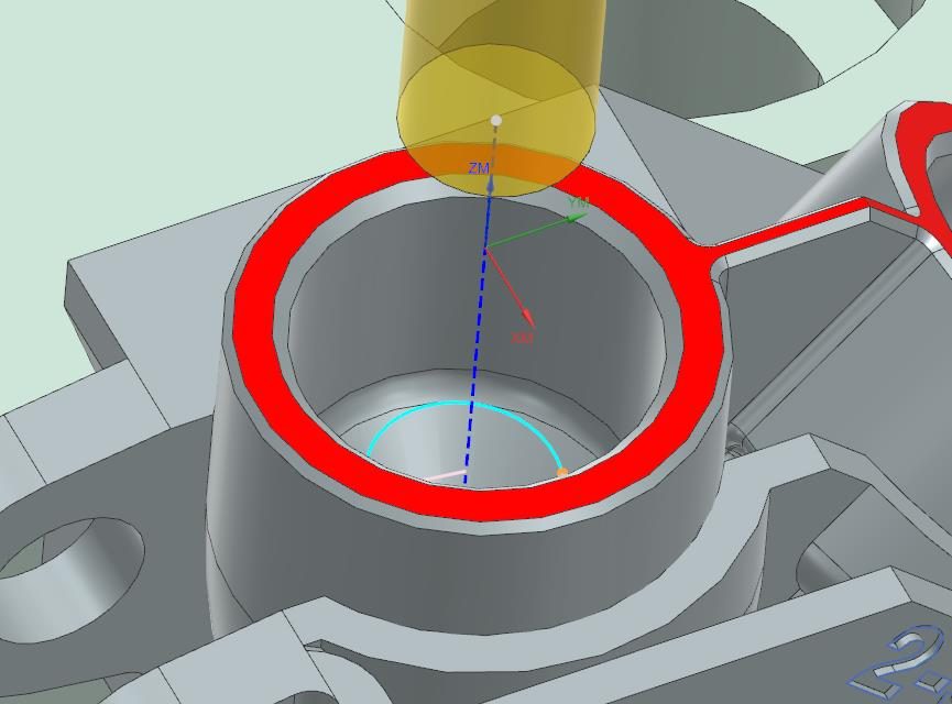
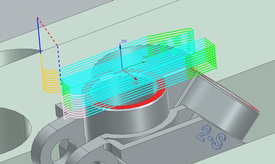
    Siemens NX view of the generated floor-facing toolpath, drawn as coloured lines above a cylindric boss on the valve body
    NX output · virtualFloor facing toolpath in Siemens NX (report Fig 12).
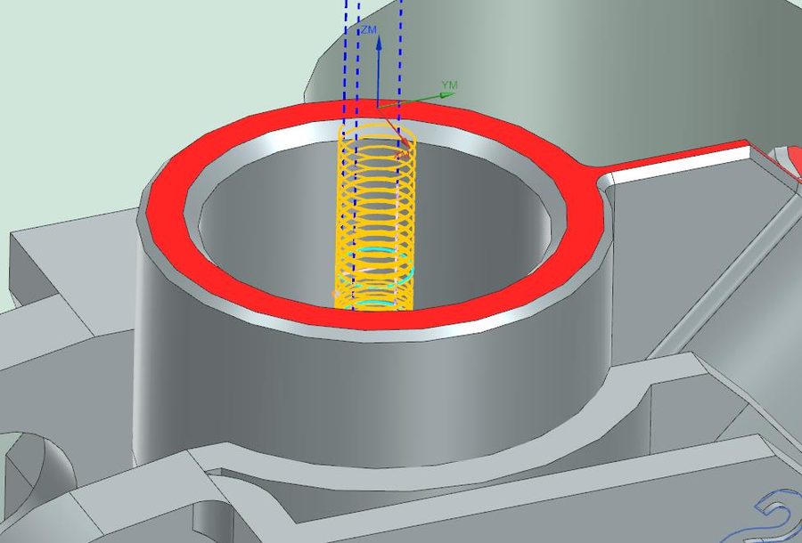
    Siemens NX view of the generated planar-milling toolpath, a coil-shaped line inside a bore
    NX output · virtualPlanar milling toolpath in Siemens NX (report Fig 14).
    Siemens NX view of the generated threading toolpath, a curved line at the bottom of a bore
    NX output · virtualThreading toolpath in Siemens NX (report Fig 16).
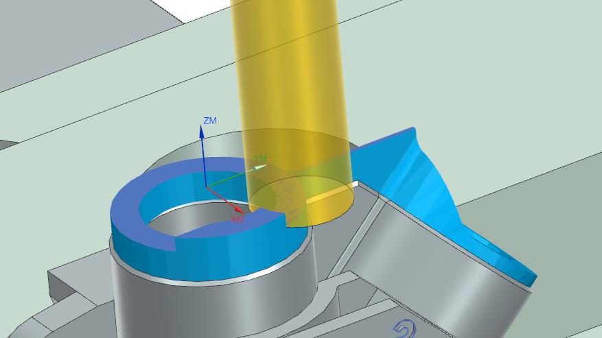
    Siemens NX simulation of floor facing: a yellow tool above the boss, removed material shown in blue
    NX output · virtualFloor facing simulation in Siemens NX (report Fig 13). Simulation only; no part was machined.
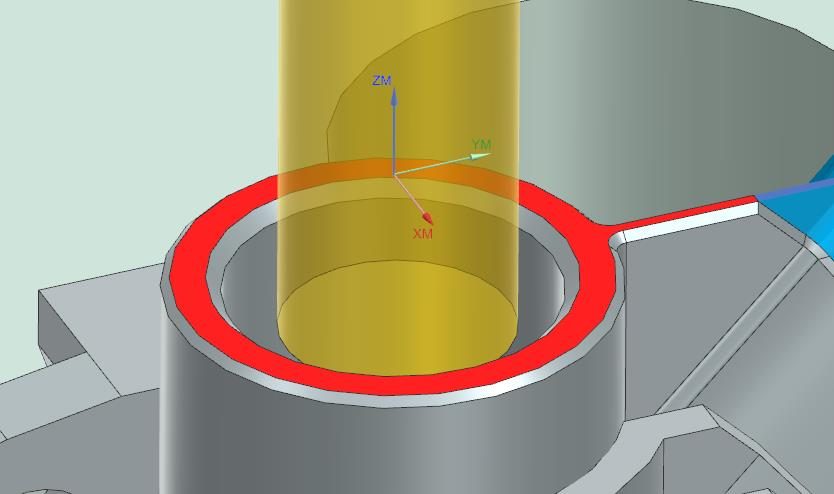
    Siemens NX simulation of planar milling: a yellow cylindrical tool inside the bore
    NX output · virtualPlanar milling simulation in Siemens NX (report Fig 15). Simulation only; no part was machined.
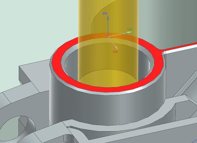
    Siemens NX simulation of threading: a yellow cylindrical tool at the opening of the bore
    NX output · virtualThreading simulation in Siemens NX (report Fig 17). Simulation only; no part was machined.
    5 · What was evaluated

    Evaluated virtually, not validated physically

    The evaluation was on screen: toolpaths, simulation and collision checks in NX CAM. None of it was compared with a machined part, because none exists.

    Simulated / virtual · done
    Physical · not done
    Toolpaths
    Generated in NX CAM for floor facing, planar milling and threading.
    No toolpath was run on a machine.
    Material removal
    Each operation simulated in NX CAM.
    No part was machined. Nothing was cut or measured.
    Collisions
    Collision checks in NX CAM, including the integrated fixtures.
    No physical fixture or machine check.
    Cutting parameters
    Planned values used as simulation inputs.
    Not verified by cutting.
    Vibration
    Considered in the literature only.
    No vibration simulation and no measurement.
    Surface quality, dimensional accuracy
    Not assessed in simulation on this page.
    No experimental validation.
    6 · What was not done

    What was not done

    Physical machining trials were not conducted. No part was machined.
    • No physical machiningNo part was machined on any machine, so there is no measured outcome.
    • No vibration simulation or measurementMachining-induced vibration was considered in the literature only.
    • No experimental surface-quality validationNo surface was produced or measured.
    • No dimensional-accuracy validationNo dimension was measured on a machined part.
    • No experimentally validated parametersCutting parameters were planned inputs to the simulation, not verified by cutting.
    • No G-code or post-processor claimThis page makes no claim about G-code, post-processing or running a machine.

    The skill shown is virtual CNC/CAM process planning. It is not machining experience on a machine.

    7 · Technical summary

    Technical summary

    Part
    Additively manufactured hydraulic valve body (laser beam melting)
    Material
    SS316L
    CAD / CAM
    Siemens NX CAM
    Operations
    Floor facing · planar milling · threading (thread milling)
    Process type
    Virtual CNC machining process and simulation: toolpaths, simulation, collision checks
    Validation scope
    Virtual only. Physical machining trials were not conducted; no experimental validation.
    Project
    “Additive Manufacturing of LBM Parts”, TH Rosenheim, 03/2024–08/2024, individual Master's project
    Domain B · CNC & CAMAcademic · virtual only

    Email

    rathore.mihirraj@gmail.com

    LinkedIn: mihir-raj-rathore

    ← Back to the portfolioPortfolio · Updated Oct 2026